Getting the Heat Right for Smart Meter PCBs
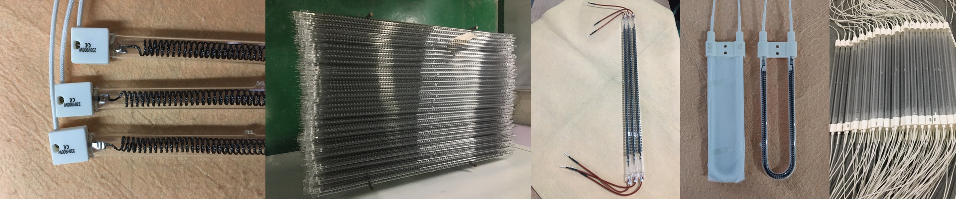
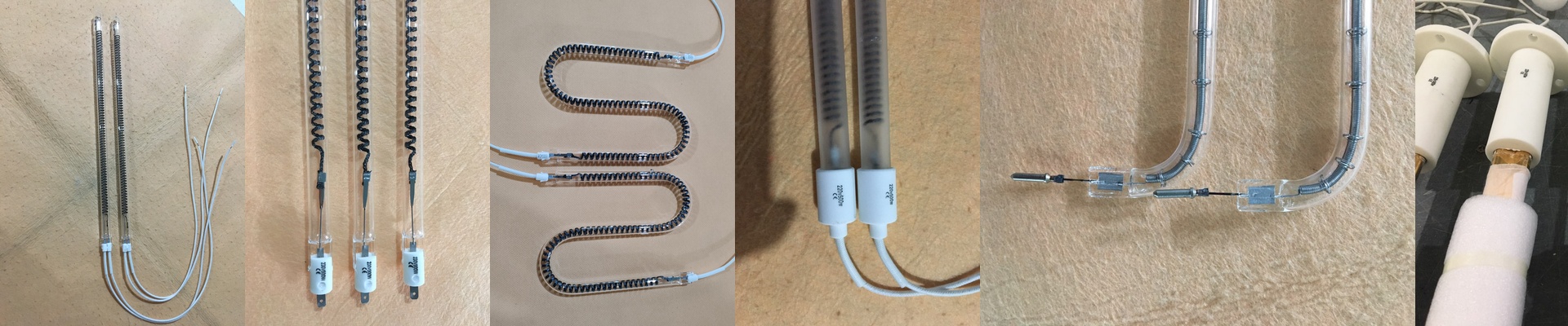
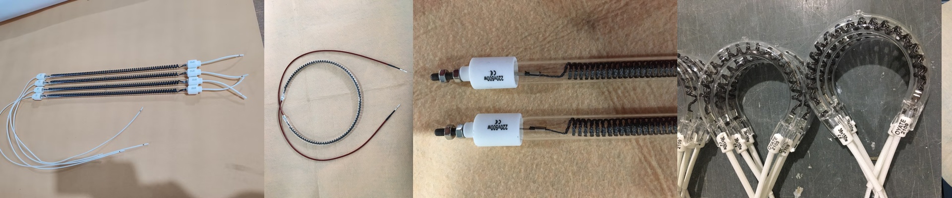
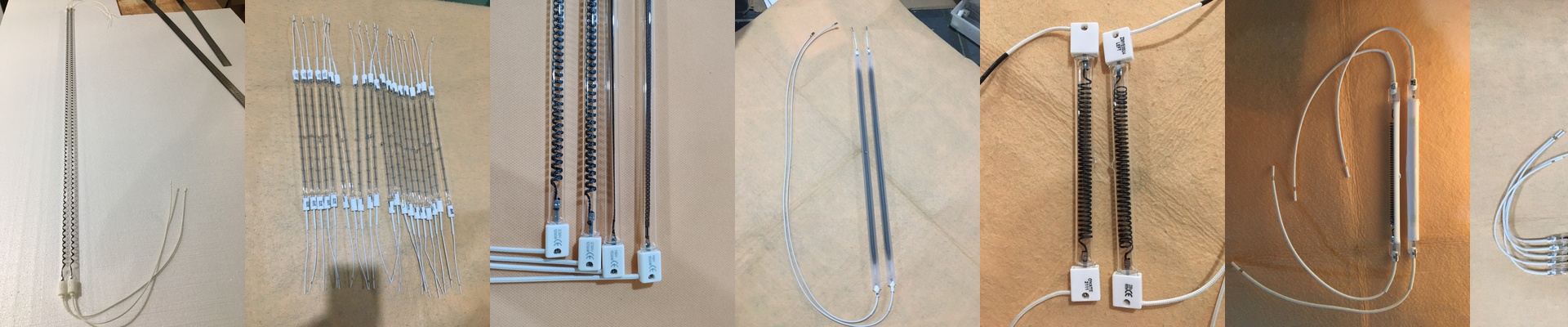
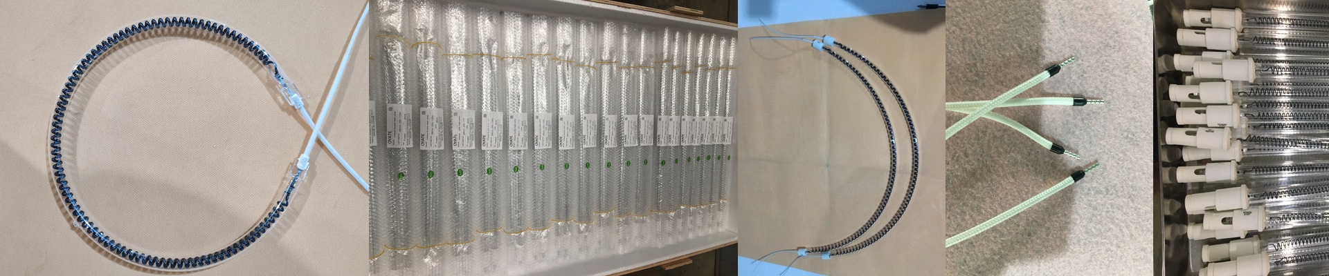
When you’re working with smart meter PCBs, just “throwing heat” at the board doesn’t cut it. You can’t just blast it and hope for the best. We build our heating lamps to hit a very specific spectral window. Why? Because you need wavelengths that can actually get through the solder mask and hit the substrate without frying the components on top. It takes a bit of a balancing act with the halogen cycle and the quartz dosing to make that happen. The science behind the glow Most lamps you buy off the shelf just dump energy everywhere. It’s messy. We do things differently. By tweaking the filament and the thickness of the quartz, we shift the energy so it matches exactly how the PCB materials absorb heat. If the spectrum is too wide, you’re basically just heating up the air in the room. Too narrow? You’ll end up with cold joints. We’ve found the sweet spot where the heat goes straight into the copper traces. The hardware side of things These lamps are designed for those tight, high-density footprints. Since you’re likely dealing with rapid ramp-up times, we used reinforced electrodes. It stops the lamps from burning out when you’re power cycling them constantly. One heads-up: these tubes pack a lot of punch for their size. You’re putting out massive energy in a tiny space.**Make sure your cooling fans are up to the task.**If your chassis can’t pull the ambient heat away from the ends of the lamp, your connectors are going to die a lot sooner than they should. Making it work in the real world We kept the fittings standardized. That means you can just drop these into your existing lines without a headache. The big goal here is consistency. We test every single batch to make sure the output doesn’t drift from one tube to the next. No one wants “hot spots” moving across a conveyor belt. You want every single board in the batch to hit the exact same temperature profile. It’s not about guessing. It’s about making sure it works every single time.