Getting the Heat Right for Smart Meter PCBs
Smart meter PCBs are a nightmare to heat. You’ve got a ton of components crammed into a tiny space, and trying to get the temperature even across the whole board during curing and soldering feels like a constant fight. We don’t look at our heating lamps as just “bulbs.” Think of them more like precision tools. The goal is to hit that perfect temperature window—hot enough to do the job, but not so hot that you torch the substrate.
The Trick to Targeted Heat
It’s all about the infrared spectrum. We tweak the wattage and voltage so the heat actually sinks through the solder mask and hits the joint. The danger is the plastic housing around the meter. If you push too hard, you’ll delaminate the board. If you’re too timid, you end up with cold solder joints that fail later. It’s a balancing act. You want a tight, steady thermal gradient across the board. No hot spots, no dead zones.
The Gear Under the Hood
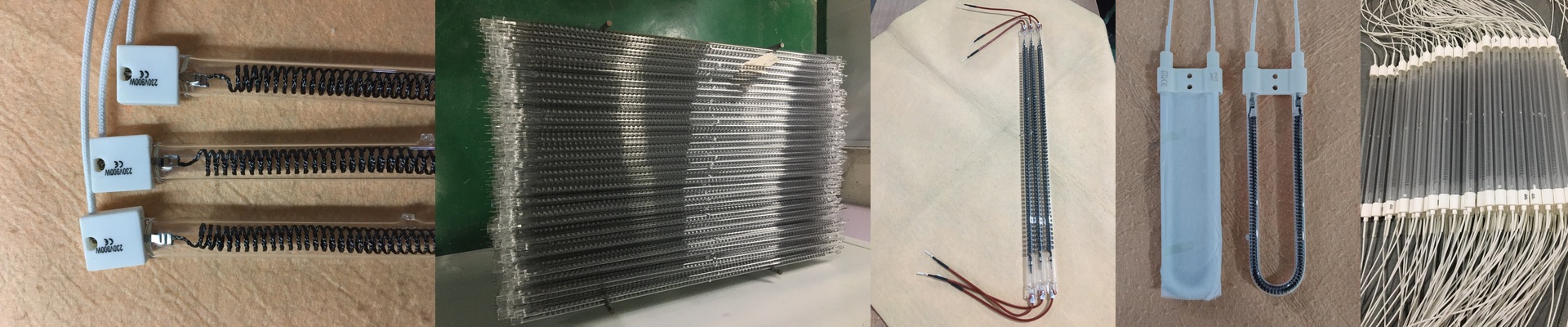
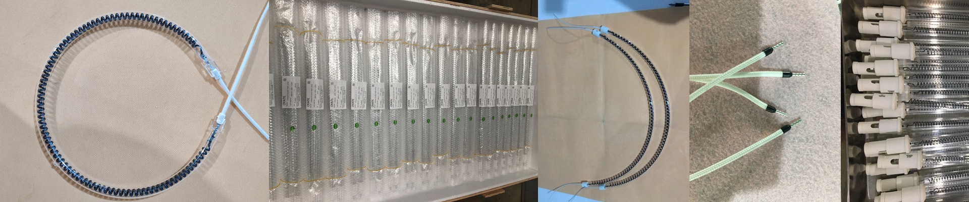
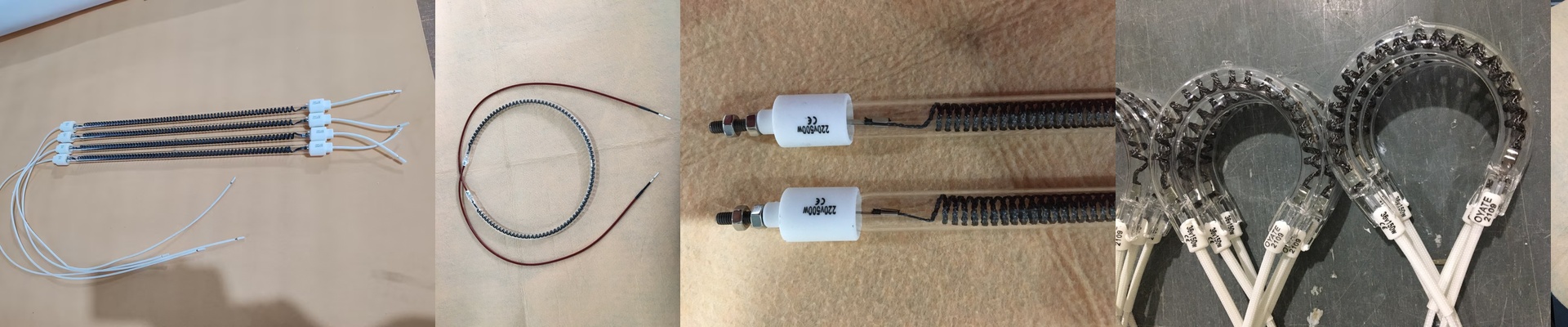
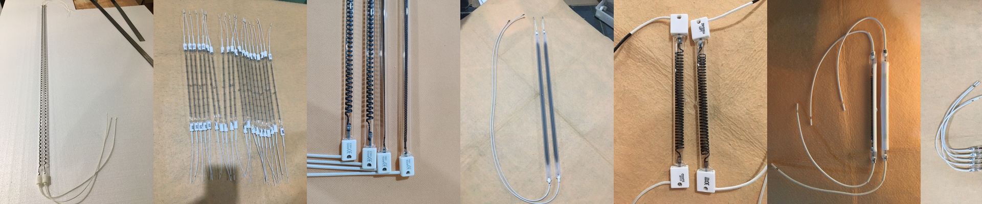
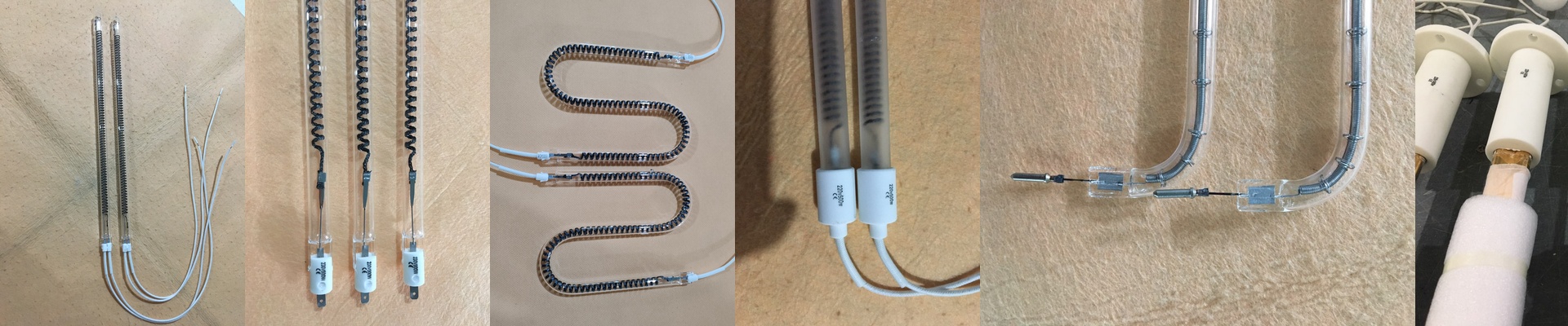
We use high-purity quartz for the envelopes because nothing is worse than a lamp burning out mid-shift. The filaments are built for a fast ramp-up, which is a must when your assembly line is moving at full speed. Plus, we kept the connectors standard. You can just swap them in. No need to mess around with your mounting brackets or redesign your setup. But the real secret is the coating. It shifts the emission spectrum to match how PCB materials actually absorb heat. Instead of the energy bouncing off the board and wasting power, it goes exactly where it needs to go.
The Trade-offs (The Honest Part)
Here’s the thing: high heat density has a price. When you crank up the wattage to speed up your throughput, the machine chassis starts to soak up that heat. That’s where your exhaust fans come in. If they aren’t up to the task and the air around the lamp housing gets too stifling, your lamps are going to die a lot sooner than they should. Keep the airflow clear. Your hardware will thank you.